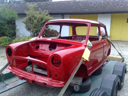
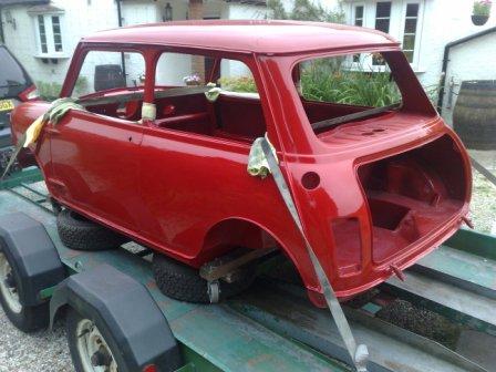
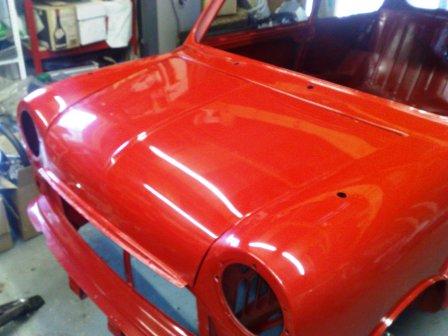
Here it is, the finished shell in all it's glory


|
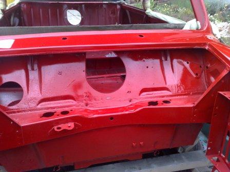
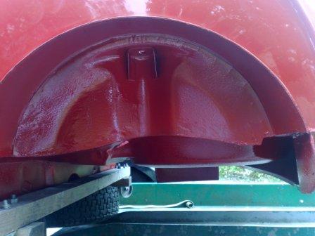
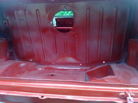
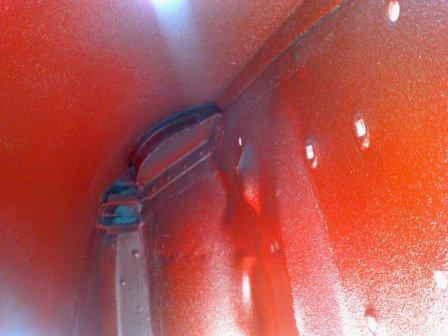
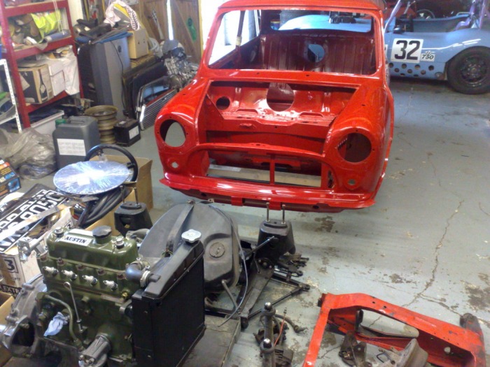
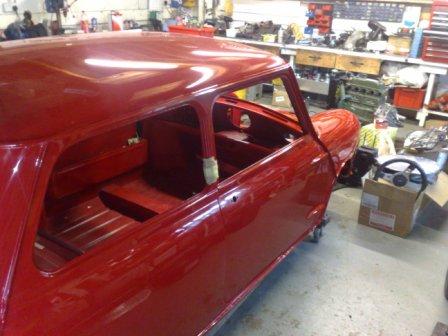
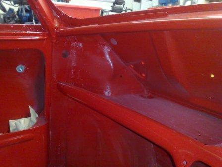
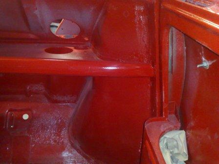
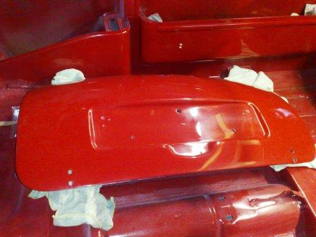
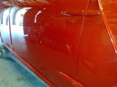
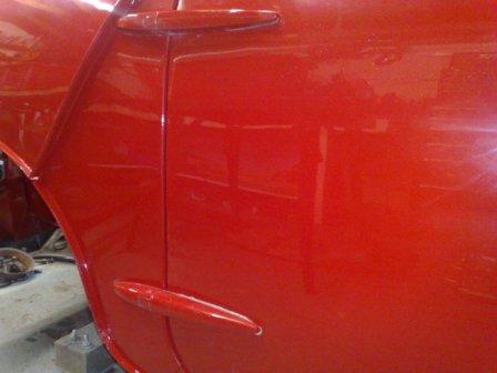
Time is flying (I must be having too much fun!) which means it's been a while since my last blog and I have some catching up to do. I also have a very exciting development to reveal..... Lets start with doors and boot, the easy one first, the Drivers Door...... The original door was in a pretty sorry state, not only was it rotten in the usual places at the bottom, but it had also failed with a crack where the glass frame joins the body of the door. For this reason, and also because I had a very good drivers door "in stock" I decided not to repair the cars original door, but to simply replace it with the good one I had. I then spoilt myself some more with a set of brand new hinges and gaskets. The pictures below show the drivers door in place. 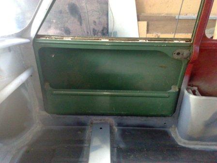 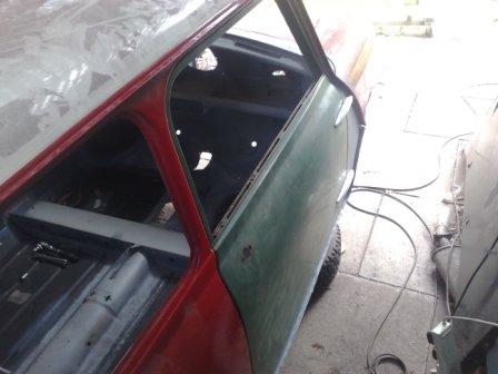 The passenger door was a different story, although not as bad as the driver's door, I didn't have any easy way out so a repair was in order. The rot had attacked both the frame and the skin at the bottom, very typical for mini doors, both early external hinge type and the later internal hinge ones, there are so many moisture traps, its easy to see why they are a weak link. To make sure the repaired frame remained straight during the repair, I left the skin in place while I cut the rotten section out. I then formed a new part from sheet steel, and welded it back in place. using the original skin as a guide. 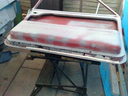 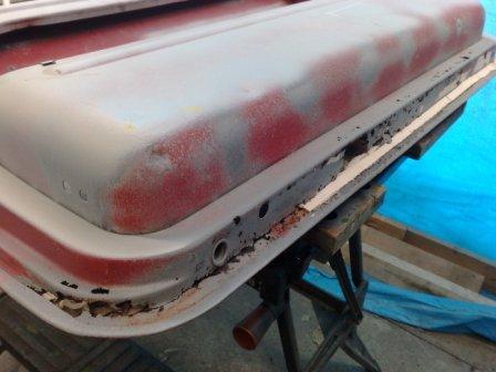 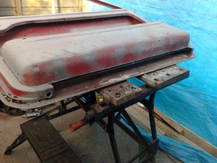 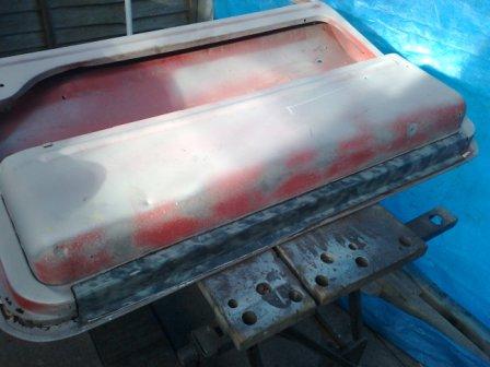  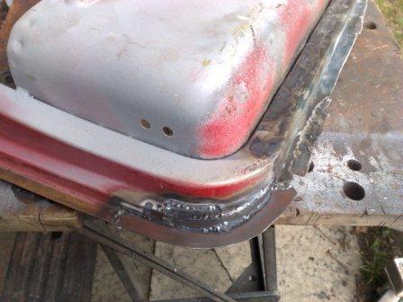 Once the frame was solid I carefully removed the skin ready for the new one to be fitted. I know some people consider fitting door skins to be a bit of a black art, but there really is nothing to be scared of. With a bench covered in a protective layer of old carpet and some old fashioned patience, there is no reason your new skin won't be as good as the original. I have to say though, I don't use a special folding tool to form the edge as these tend to mark the skin on the outside as they brace and leaver against the vulnerable surface. I use a flat panel hammer and a dolly wrapped in thick cloth and gaffer tape (effectively giving me a nearly solid 'dead-shot bag'). The first job however is to add a bead of fixing sealer. I used a product called "Stix-All" for the first time on this door and I have to say I was impressed. It’s a non shrinking sealer / adhesive recommended for bonding metal parts (as well as almost everything else! Now it's time to get the skin in the right place, for this I offer the frame up to the body, and hold the skin in place with some grips (with protected jaws). Once I'm sure the gaps round the door are even, I tack weld the skin to the frame at the front and rear. Then the part that requires a little patience begins, folding over the edge of the skin to secure it in place. My recommendation here is to work round the whole door in small steps, bending the flange by about 10 to 20 degrees on each pass. The corners are the tricky bit, but with care they will fold down flat and hold the skin securely. Once folded there are a couple more welds to make at the top near the glass frame, and that's about it. 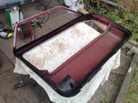 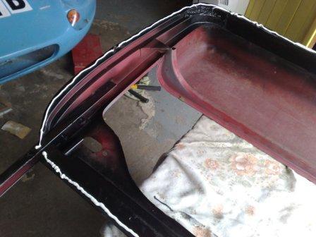  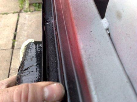 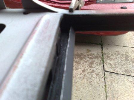 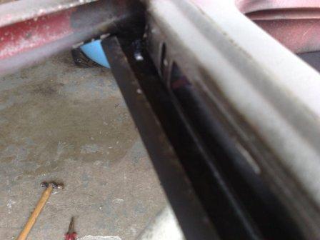 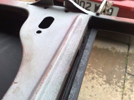 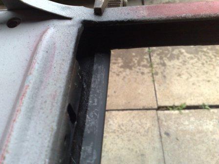 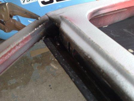 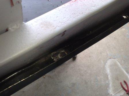 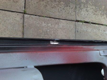 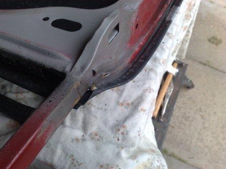 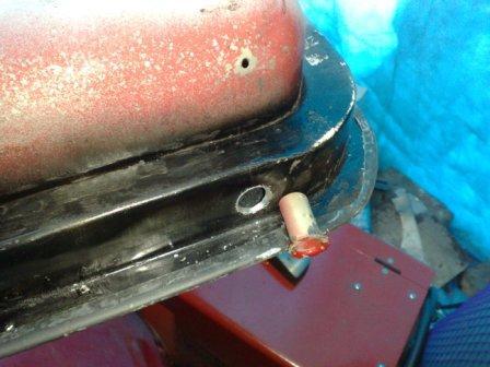 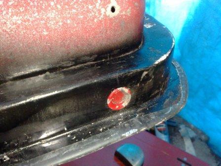 To finish off I fit the drain tubes in the base of the frame and attach the door to the shell. The final panel to receive attention is the boot lid. Being an early car the boot lid is a one piece part with a skin much the same as a door, and to go with it, there are much the same moisture traps. Evident here by the line of rot through the lower part of the outer skin along most of it's length. Once the paint is removed the full extent of the job is revealed. It's not bad enough to justify a new skin so I have made a repair in much the same way as the door frame. I first remove the rotten material then make small sections from steel sheet and weld them in place, before grinding back any excess to leave a finished surface ready for paint. 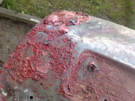 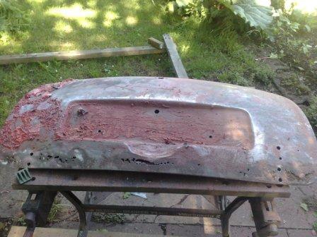 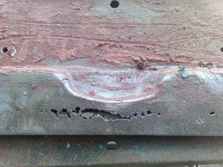 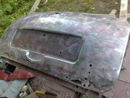 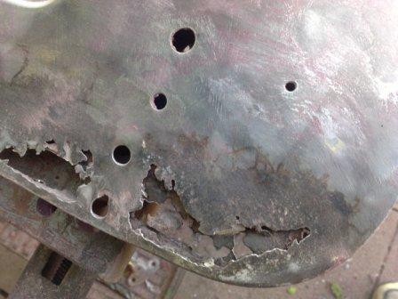 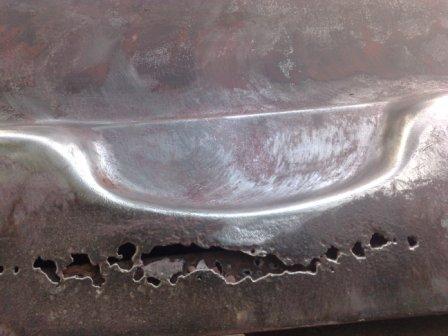 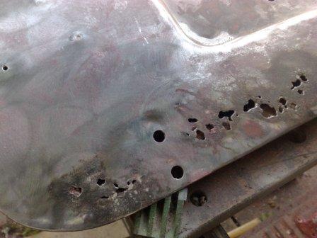  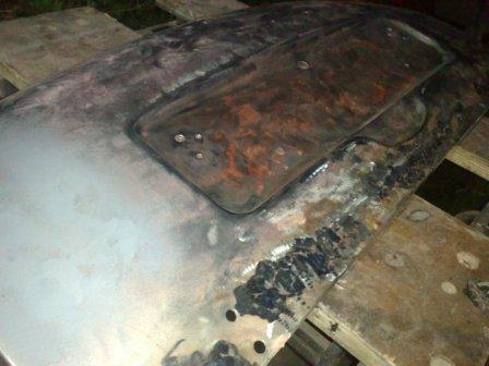 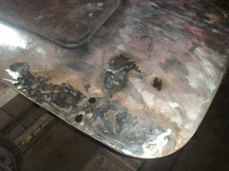  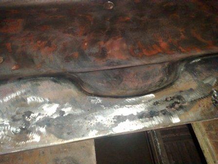 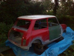 And there we have it, all finished and ready for paint. They say that you should know your limitations, and I know my limitations are reached when it comes to a good paint finish. So the shell is loaded onto the trailer and sent away to my friendly neighborhood paint shop. I spent some time considering whether to keep the white roof or to go for the whole car in Tartan Red. As mentioned at the start of this blog, there is a very exciting development to reveal, and in doing so, you can see my color scheme choice! My decision was made when the Heritage Certificate arrived for the car, declaring it was all Tartan Red when it left the factory in 1969. 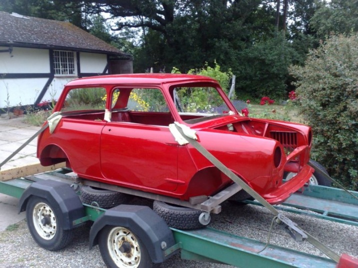 It's been a little while since my last blog, but that doesn't mean that things have been standing still on the 1969 Mini Cooper restoration project, quite the contrary in fact, so let’s take up the story from where I last left off.... Having fitted the left hand floor, sill and subframe mounting panel, next up was the left rear wheel arch. Again the condition of this side of the car was slightly worse than the right, but fortunately once the rotten arch was carefully removed the extent of the rust penetrating into the surrounding panels was minimal. These pictures below show the arch during and after removal. The during pictures show how it's best to carefully remove the metal around the original spot welds, leaving the return on the panel that is to stay in the car. This way the new panel can be fitted and welded in the same way as it would have been originally. 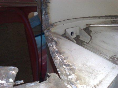 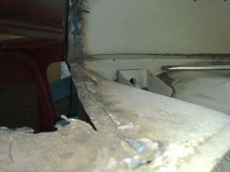 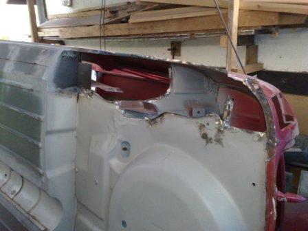 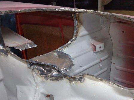 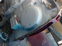 After the new arch was welded in place I removed the rear valance. This was a little extra job I added, it hardly needed replacement, but the corners were showing signs of rot and it was in fact a replacement part that had not been fitted particularly well so I decided to replace the whole thing. The new panel is not expensive and it's and easy part to fit. I want to not only replace the rusty bits but also fix any previous workmanship issues as I go through this project, so it made sense to make the effort. With the new valance in place the welding on the underside was complete. I then concentrated on the finishing touches before the car could be stood the right way up again. Finishing touches in this case being seem sealer. I have tried various seem sealers in the past and by far the best are the brush on types. It doesn't make sense to scrimp on the quality either, here I'm using a 3M product that my local trade car body material supplier recommended as the best. It certainly went on easily and was also easy to brush into a factory type finish. 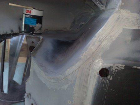 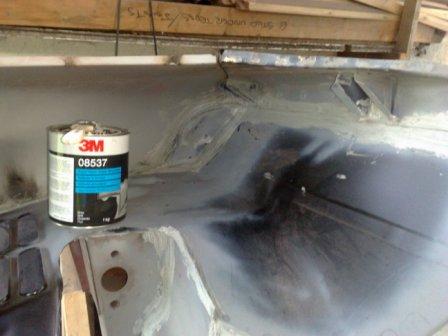 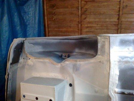 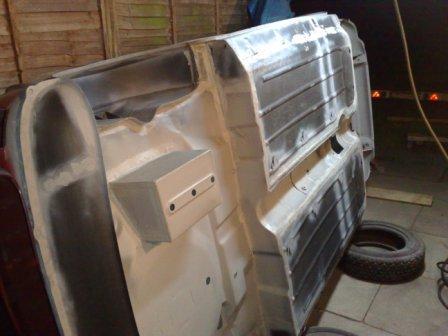 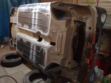 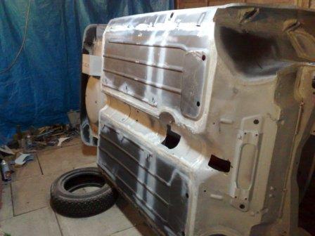 So the car could finally be stood back up the right way! There were still a couple of jobs to do on the shell before I could move onto the closing panels (doors, boot and bonnet etc). One such job being the transplant of the radiator surround from the old inner wing to the new, as shown in the series of pictures below. (With just a small repair section being required in the lower section) 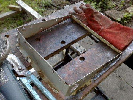 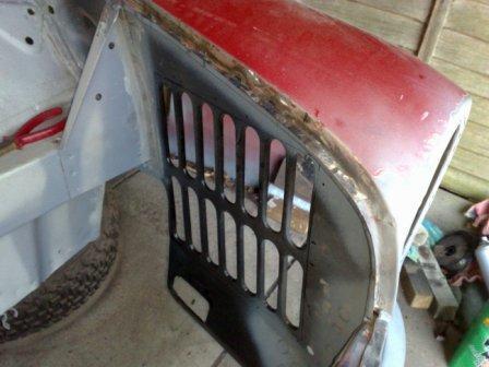 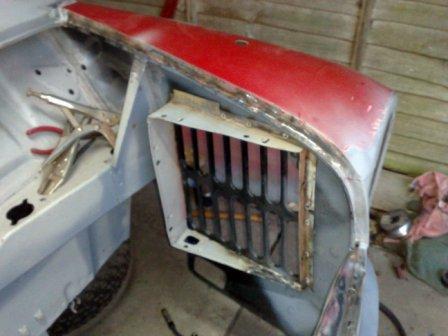 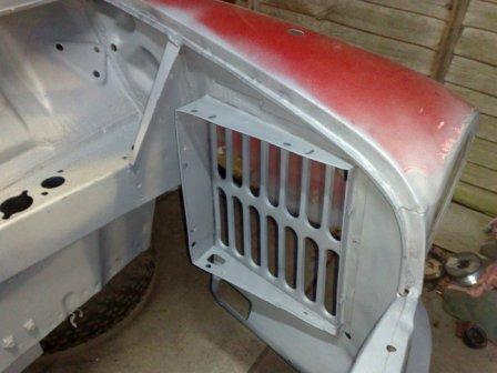 With the radiator surround in place the seems inside the car were sealed and the whole shell was given the once over for anything I had missed. I could then finally declare the shell "Ready For Paint". Phew! If you have been following the blogs or if you read on down through them you will realise just what a milestone this is. Having said that, it's not going anywhere until the doors boot and bonnet have been sorted out and that's what I will tell you about in my next blog, so until then........ happy restorations!  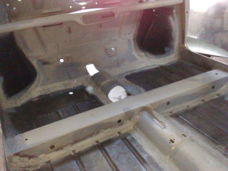 After my last Blog post, my motivation was up, the chance to finish the right side of the car was definitely in sight. The final area that needed to be sorted out was the corner of the boot floor and with it the corner of the body and rear valance mounting return. As you can see in the pictures this all went well and the corner was pretty quickly solid and sound. 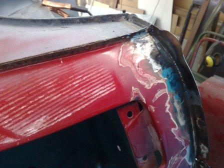 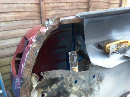 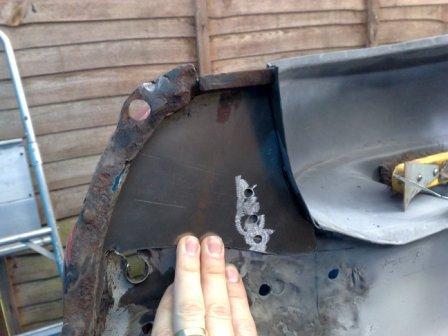 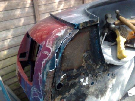  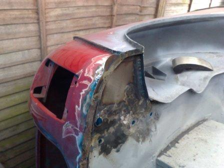 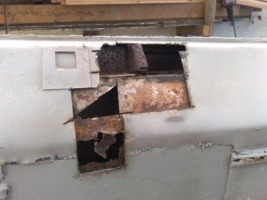 So it was time to roll the shell over and start work on the left side. But as I was getting ready I realised that all the dirt, grinding grit, dust and remaining shot blasting sand had been falling and gathering on the lower side (the left). Not a problem to clean up where I could see it, but there was also a whole load that was trapped in the cross member, which I didn't want to stay there as the shell rotated. So I cut a hole through the sill and let it all out. There was a fair quantity in there so I'm glad I did. The picture here shows the hole and also the blocked up jacking point in the sill (not much use to anyone!). Then finally, after a good clean up of the rest of the car and my work space it was time to roll the shell over. 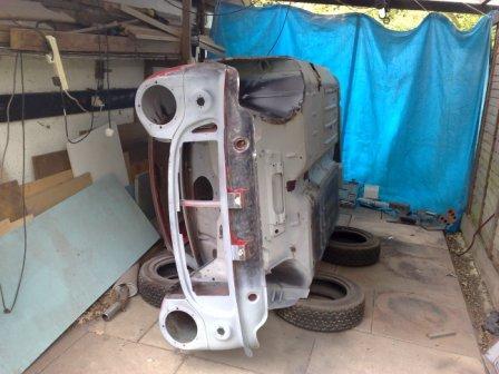 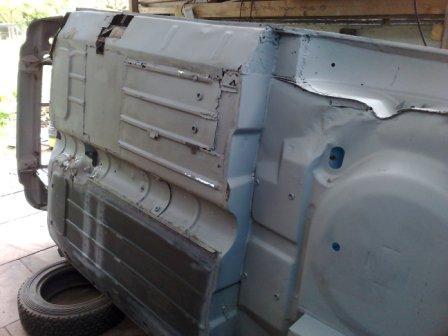  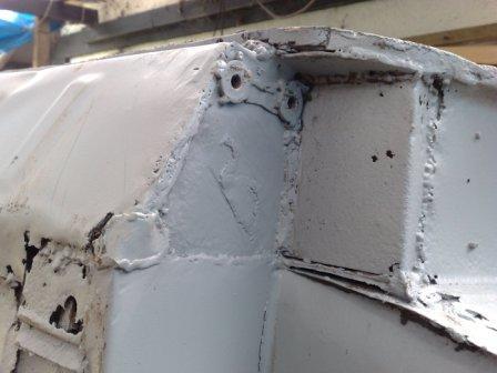 As you can see the condition of this side is very similar to that of the other, the rot is evident across the whole floor pan and has also started the "nibble" into the parts above the floor. The cross-member and the companion box are if anything slightly worse on this side. Which means slightly larger fitted repair sections will need to be made. The next shots show the removal of the sill and floor pan. The first two pictures illustrate just how much of the shot blasting sand has found its way into the inner parts of the body through the rust holes. So my tip of the day would have to be "Don't use shot blasting to strip your car unless you are going to open every cavity during the restoration process". The last thing you want is to be carrying 10kg of sand round for the rest of the car's life! 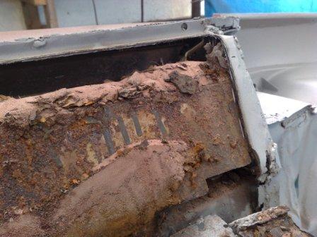 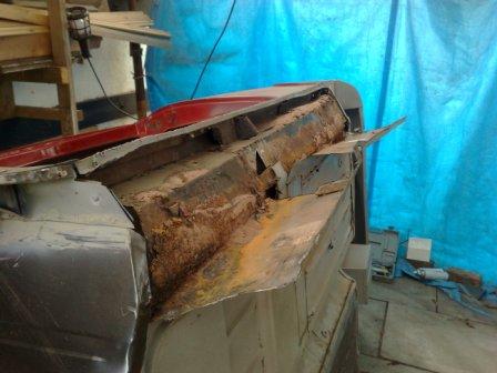 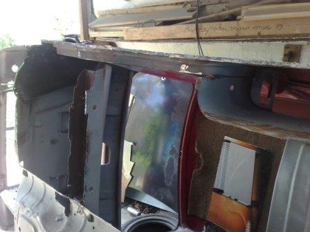 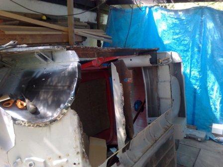 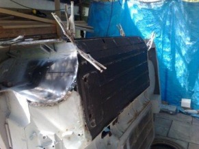 With the old floor and sill removed I can then start the process of trial fitting the new panel. As with the other side I'm using a Heritage half floor and 4" sill panel assembly. These come with the Jacking point and the piece of the cross member that sits inside the sill (to reinforce the jacking point), already fitted. The 4" sills are what would have been fitted to this, a Mk2 Mini, originally. Once in place I can then make the templates for the sections of cross-member and companion box that I have had to cut away. These I then transfer into metal sheet and carefully file to a final fit, before they are welded in place. To finish the job I grind the weld back so the repair is invisible.  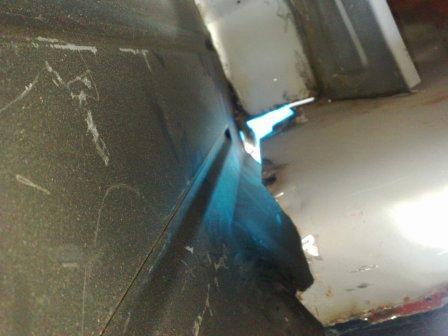 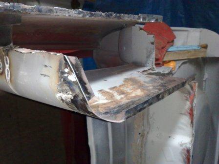 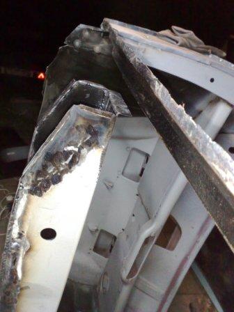 Then, once all the areas that won't be seen again are given a good coating of rust protection it's time to weld the floor into place. As always before and during the welding process I'm careful to check the alignments and dimensions to make sure that there is no heat deformation and that all the critical points are in the correct position. 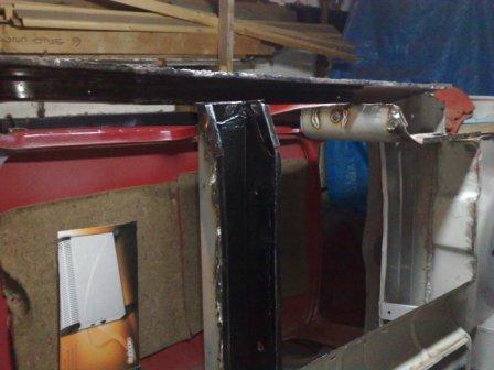  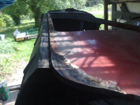 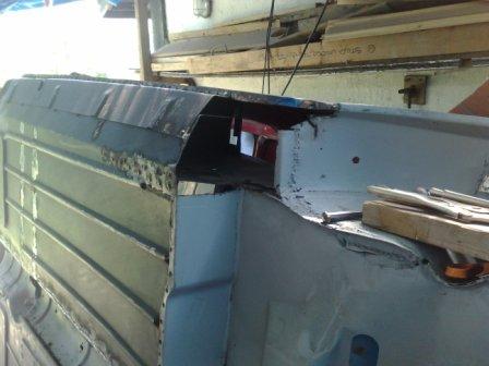 Next it's time to fit the Subframe mounting panel. As you would imagine the alignment of this is absolutely critical. If it's wrong, the Subframe will not sit straight in the car and the result will be a Mini that looks like a crab when it drives along the road. So to get this right, I use the rear subframe as a jig, which picks up on the three mounting locations that remain on the body. With the subframe secured tightly to these (I have fitted new rubber bushes to ensure a tight fit), There is only one place the fixing panel can go. Which is interesting because it needs a little modification to allow it to fit in this position. So I take a number of measurements to make sure I'm doing the right thing before I'm convinced the panel is the part that needs to be modified (it's only a matter of bending along a slightly different line). Then after another check it's ready to be welded in place. (Always remember, just like your Dad told you, if you measure twice, then measure again, you'll only have to cut (or in the case weld) it once!) And that brings me up-to-date! If you're reading this for the first time please find me on Facebook or Twitter (Rob Russell) and you will receive notification when I add more to the Blog. Which will be very shortly I hope - after all my motivation is still high, driven by the good progress being made, so I can't slow down now! 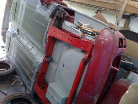 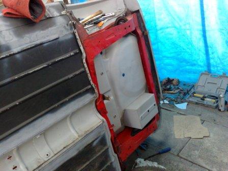 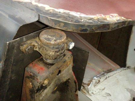 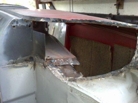 Here's another update, a fairly quick one this time, to show you the new left rear wheel arch and subframe mounting. Which means the left hand side is virtually finished! Wow, it does feel like a long haul, but once the shell is flipped over and I'm into the right hand side I hope I will be able to see the end of the grinding and welding tunnel! Here are some pictures showing the new subframe mount. I used the subframe it self to align the fixing holes but unfortunately my camera had a freaky day and I have lost the shots of that operation. So if you can stand the suspense, I'll have to record the process when I fit the simila panel on the other side.  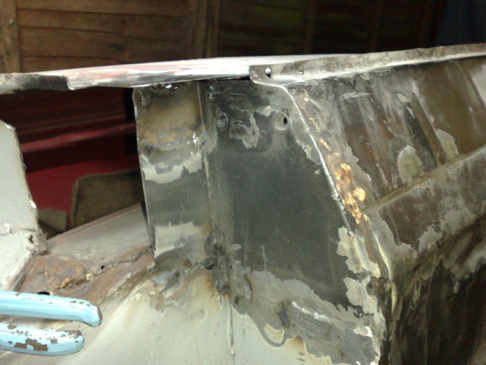 Next up is the rear wheel arch, as you can see it was in a pretty dire state. As with the rest of the car it had been patched, but the rot was on display for all to see. Why it had not been cut out before the patches were fitted I can't work out? Not to worry though, it will all be replaced, rot, patches and all! These are a few "Before" pic's.  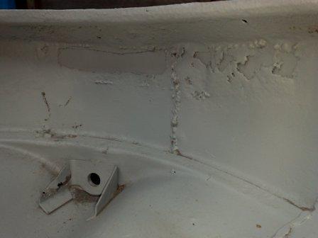 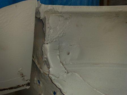  The removing process is not particularly straight forward when it comes to Mini rear arches, mainly because they 'key' into so many of the surrounding parts, the rear 3/4 panel, boot floor, seat back, subframe mount panel, rear seat pan, the 'companion bin' and also a couple of strengthening gussets that run the load from the rear subframe mount up into the arch. So care is the order of the day when the grinder is "at large". The pic's below show what I have ended up with....   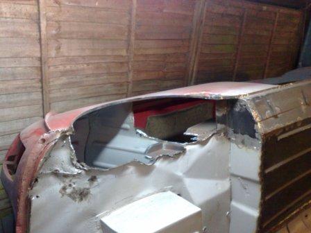 During the removal of the rear arch it became apparent that the bottom corner of the 3/4 panel was in a rather sorry state. That's actually an understatement, the truth is it had been well and truly bodged! Using some bent bits of metal (shown in the first picture below) which were basically held in with body filler. So I broke the filler out and stripped back the rusty metal until I was back on solid ground again. It was then a case of making up a template in cardboard, transferring this into metal and welding it in place. Because this section has a return on it (which the side trim fits to) I then cut a strip of sheet metal and welded it into position. To produce the infill piece with the return as one single piece would have been pretty much impossible without making a tool to use in a press. However with good welding my method is just as sound but it took far less time. 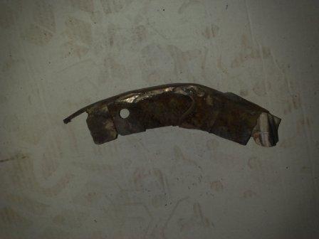 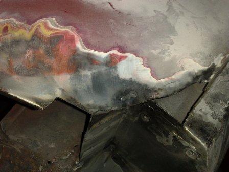 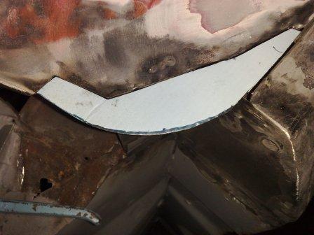 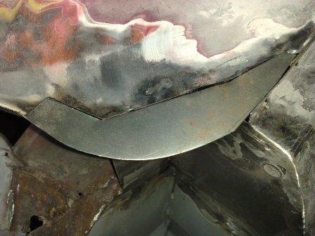   I then had some making good to do, to make sure all those panels that key into the rear arch were in pristine condition. This meant a few more infill panels and some more repairs to return sections. The shell, ready to receive the wheel arch is shown in the first two pics below, while the second two show the arch being fitted. Note the holes for the spot welds (or puddle welds). The ones on the inside edge of the arch pick up the seat back and strength gussets. And there you have it! the right side is pretty much complete - just a little work on the rear corner and valance before i can flip the shell over and start the flooring process over again. Hopefully I will be well into that for the next blog update.  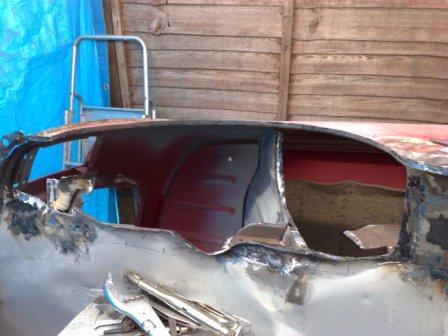  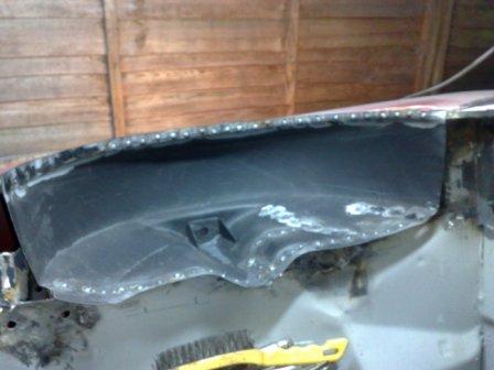 The grinding and welding has been carrying on unabated over the Bank Holiday Weekend, sorry neighbors! (although the rain probably kept most of them safely indoors and behind double glazed windows!) So what's been happening, well...... The front panels (two wings and front nose part) have been welded into place, using the front subframe as a jig and picking up the inner wings in various places. I also took some time to strip the paint completely from the front panel, this is probably me just being pedantic, but I think the build up of a number of paint layers over the years tends to dull, or blur if you will, the edges of the panels that are on show at the front of a Mini, round the head lights for example. By starting the paint process from bare metal the end result is much more "in focus" and of course original looking too. Once this was complete and i was a nice shade of pink from the paint dust it was time to get on with replacing the sides of the floor pan. I'm fortunate because the exhaust tunnel arch has virtually no rust evident, so I can leave that structure in place and also the cross member that the seats fix to is in a simila condition. So just like with the front panels, if I tackle one side of the floor at a time the body remains ridged and there is no chance of distortion. To get good access I have rolled the body onto one side, carefully resting it on some old tyres at the strong points in front and behind the door and at each end of the roof. I can now clearly see the right floor panel that's going to get the attention first.  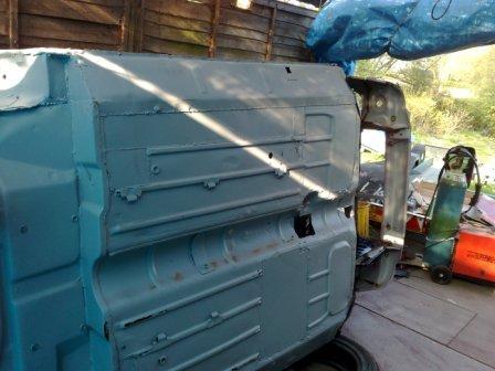 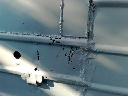 Once safe on it's side it's time for the "Flintstone" conversion! I carefully cut out the floor to open up large holes infront of and behind the cross member. Then I go round the whole panel in detail and grind back to the solid parts of the upper panels. Unfortunately the rot has taken the return sections of the pocket next to the rear seats and a small section of the cross member. These will need to be templated and made as fitted sections that I can weld in place. However on the whole the rot is restricted to the floor. The first picture shows the same story that I have found elsewhere, in the back section there is evidence of at least three layers of sill that have been fitted over each other during the years. At least it shows the car has been used and enjoyed I suppose.  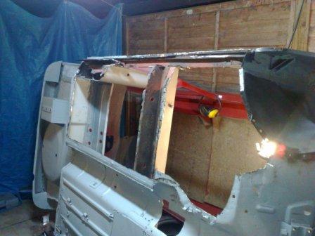  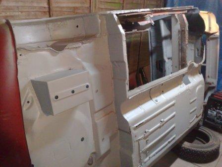 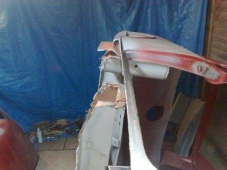 You can see in this picture that with the cross member still providing support the sill remains nice and straight. Now that the old panel is out, I can trial fit the new part. Being a Mk 2 Mini it still has the bulge in the floor where the floor mounted starter button sat in the Mk 1version (a feature to look out for if you are checking a Mk1 or Mk2 for authenticity). So I have to modify the new panel slightly to fit round this bulge and also cut it exactly to size at the joint along the exhaust tunnel. I do this by clamping it in place, then I paint along the joint with primer to give me a line that I can carefully cut along. When it's all done it can finally be placed into the completely correct position. When in place I can go about making the templates for the missing parts of the luggage box and cross member. I do this in cardboard first and then transfer the shape to a piece of the correct gauge steel sheet. It's thin enough to cut roughly with snips and then file into the final "fitted" shape. Then I remove the floor to allow me to weld them into place. The third picture below shows the gap to be filled at the bottom of the luggage box. The fourth picture shows my panel (with the correct returns) welded into position. 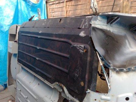 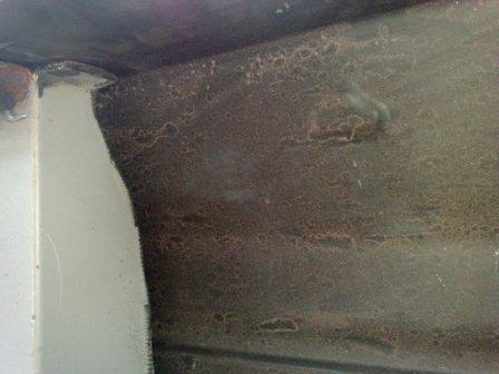  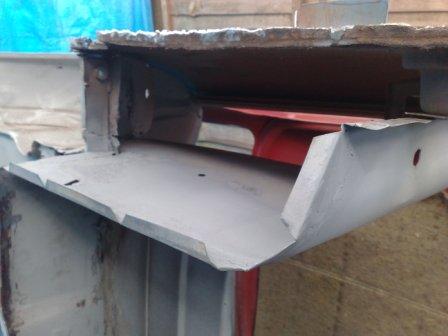 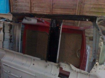 The cutting and prep work is nearly complete, all that remains before the floor is fitted is to give the areas that will not be seen again a good coat of rust protection, and then the final fit can begin. I clamp everything in place and start the welding at the front outside edge of the floor pan. This is a critical point to get right, it's where the inner wing, the floor, the bulkhead and the sill all come together, so plenty of alignment checking is needed to make sure it's all clamped in the right place (shown in the first picture below), prior to 'sparking up' the welder. The second picture shows this area complete. I then carefully work round the rest of the panel. 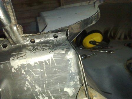  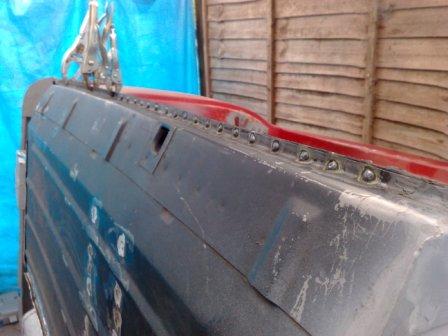 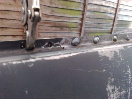 Next up will be a repair section for the rear subframe, front fixing (a notorious Mini rot spot, as mud and grime tend to collect here between the subframe and the body). But before I can do that, I strip the radius arms out of the rear subframe, to make it a little lighter to handle. It's going to be used as a jig to make sure I get the fixings in the right place (just like I used the front Subframe earlier). It feels good to use a spanner again, I've been attached to the welder and grinder for long enough! So that pretty much brings you up to date. I have to say, I can't wait to get to the point where it can go for painting. This part of the whole restoration process is quite intense, because the consequences of getting something wrong are quite high, but at the same time it's also very repetitive, not to mention noisy and dirty work. This tends to lead to a very high intake of cups of tea to keep the concentration and motivation up! Thanks for reading, please check again soon for the next installment!     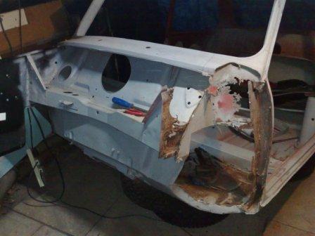 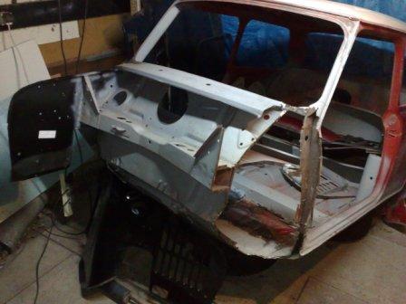 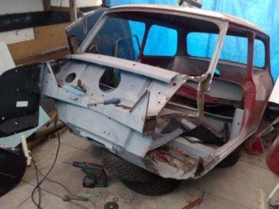 So, it’s time for the left front corner to receive the same treatment as the right. First up is the big strip back, as before I have carefully removed all the rotten metal, back to the panels that that remain solid, I’ve been careful with the grinder not to damage the return elements of these panels, so I can weld the new ones in, using the same joints as would have been there when the car was new. In this third picture and the ones below you can see the extent of the strip back on this side, with virtually the whole “A” pillar being removed. It might look extreme but even with all this structure taken out the remaining parts are not really flexible at all. This is another advantage of tackling this type of work in bite size chunks. It leaves as much of the car as possible supporting the area that’s receiving the attention. If much more had needed to come out, I would have either needed to split this area into a smaller section (replacing the inner wing before tackling the door shut for example), or I would have needed to brace the opening to ensure it would not distort during the whole process.  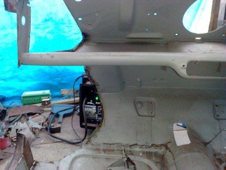 Then it’s time to start adding the new panels. The door shut is the first part to go in, although its location was quite obvious, I did carry out an over check by offering the door into position before, during and after welding it into place. Once this is in place it’s time for the inner wing. I use the same “puddle” welding technique as described in my previous post. And repeating the process from the other side, I have bolted the inner wing securely in place at the suspension bracket fixing points, which in this case is nearly enough to position the entire panel. Just a couple of grips keep the rest tight to the car along all the other joints. Here we are – it’s tip of the day time! Always check the position and tightness of the joints during the welding process, the heat can distort the panels (both new and old) so it’s important to keep an eye on what’s happening so you can react to it before everything is too solid. 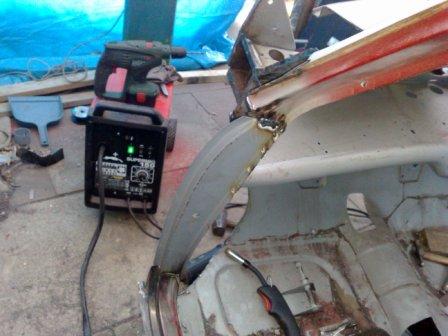 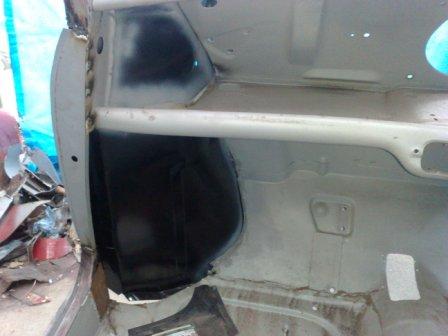 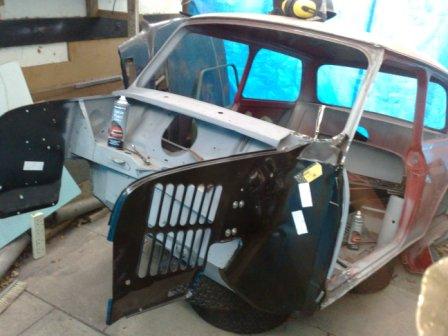  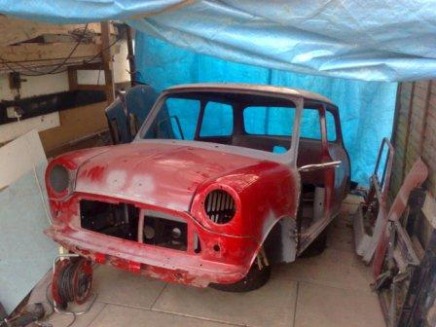 The inner and outer “A” panels are then added along with the scuttle repair panel, and there is a little "in-fill" plate that sit's under the end's of the scuttle panel (which incidentally wasn't evident on this side in the mess that was removed, perhaps a reason for the rot having got a little further here than on the right side?). And that’s it! The left side is now up to the same standard as the right.
The last thing I have managed is a quick alignment of the whole front end. I have bolted the front sub frame into place, and am using that as the jig for the location of the front panel, I can then offer the wings into position and hold them in place with grips, finally the bonnet is rested in place to make sure the shut lines will be true, and there you have it, a front end again (although not that solid just yet!) Before welding there is a little bit more dressing back of the joints to be done, to remove the last of the old panesl and the holes for the puddle (or spot) welding need to be drilled. I will also seal the seams that are difficult to reach once the outer panels are back in place. But that will have to wait for another day. Ok, so, to carry on from where I left off on the last post, the front panel and front wings were removed and I had pretty much cut out all the bad bits from the right-hand inner wing. The next job is to put the new inner wing in place and check it for a good fit. As you will see in the subsequent pictures, it's a very good fit indeed. Which is my tip for the day, with big, complicated panels I’ve found it's a false economy to buy anything other than Heritage Ltd parts. This is because they use the original BMC drawings to produce their stamping tools, so the parts are as close to the originals as you are going to get. For small or mainly flat panels you are fine to go with the cheaper brands, but the last thing you want if you're into a major restoration, is to have to take extra time to make the new parts fit. So once clamped in place it's time to mark out where the spot welds need to go. The method I use is to spray round the edges of the joints with primer. Then when removed this provides a nice 'map' of where to drill for the welds. (as shown in these two pictures) 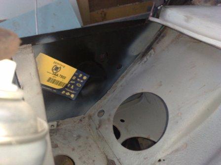 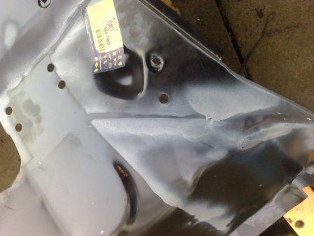 My spot welds are also called puddle welds, this is where you drill a hole in the panel of one side of the joint and when clamped in place fill the hole with weld making sure you get good weld penetration into the panel below that hasn't been drilled. This gives the same effect as the original spot welds, but they are actually significantly stronger (because they are larger) so fewer are required. For extra strength you can also stitch weld along the edge of the panels (also known as seam welding) but this is only required in particularly structural areas or if the car is to be used in some kind of competition. For this road car restoration I’m trying to keep as original as possible so I’ll only use seam welding in places where it was used on the original car. Ok, so here are some step by step pictures showing the various stages for fitting and welding in place the new right front inner wing….. 1. Drilled 2. Welded (shown from the outside) 3. Welded (shown from the inside) 4. Ground (ready for primer) 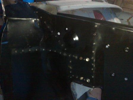  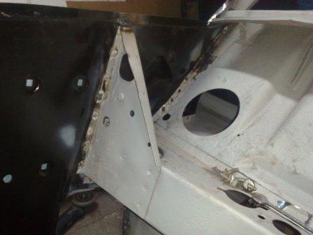 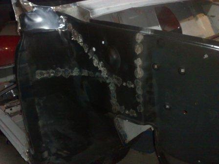 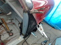 Next up is to get the inner A panel into place, this is a critical part as it has a number of alignment jobs to do. It places the door hinges as well as fixing the position of the back edge of the front wing. I hold everything into place using Grips and Clamps and even lift the door into place to check the closure gaps and hinge hole alignment, before finally making the first weld. Once held on with a few small welds the clamps can be removed and the alignment checked again. Once I’m convinced all is ok, it’s time to make it permanent by adding the rest of the welds. Note in the next picture the use of seam welds by the hinges, as already mentioned seam welds are used in more structural areas, and this is one of them. It has to take the weight of the door when it’s open so the extra strength should stop any movement at the base of the hinges. Note I’ve also drilled the flange ready for the outer A-Panel. 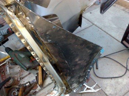 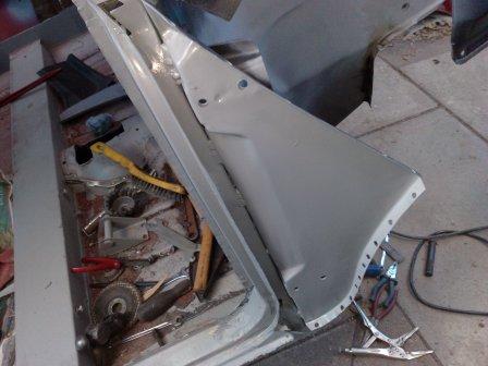 Before fitting the outer A-Panel I give all the areas that will be hidden a generous coating of corrosion protection (including the inside of the outer panel). Then it’s time to fit the outer panel and the right hand front piece of work is pretty much complete….. Phew! 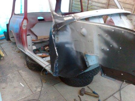 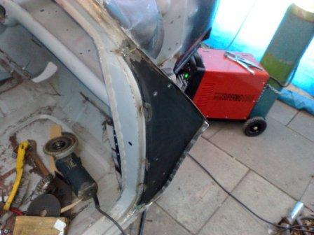 A nice change from where it was before! 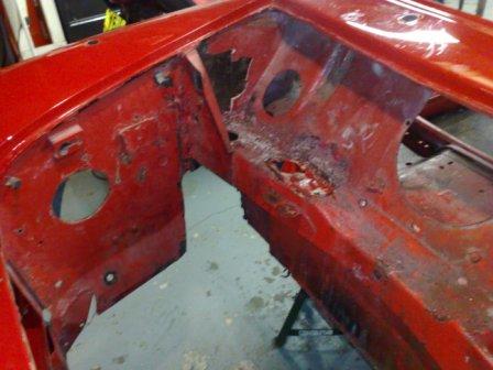  Here we are, the body has returned from the shot blasters, the paint and filler and mess has been removed to reveal the "real" car beneath, which shows both the good and the bad in all their glory! Once stripped it's been blown over with a coat of primer to protect the bear metal from light surface rust. Like the engine I'm going to tackle the body in sections. This will help keep the shell as rigid as possible when the rotten elements are cut out (I might need to make a jig to keep everything straight for some jobs too). It will also help my motivation, because, by keeping to manageable small sections of work, I can see the progress being made on a daily basis. So, the front end is going to be the first job. The front panel and the front wings are much newer than the rest of the car and they can be reused, but in order to replace the inner wings and "A" panels they first need to be carefully removed. I do this by grinding through the panels that are to be replaced and then once off the shell, I can clean up the details ready for re-fitting. Once the outer wings are removed the full extent of the rotten inner wings is revealed! 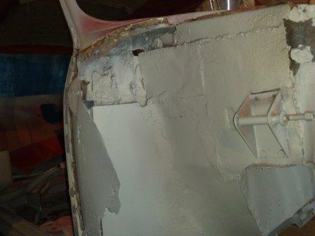 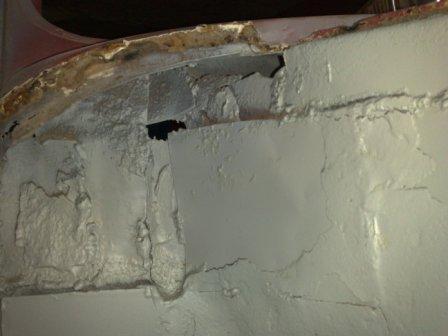 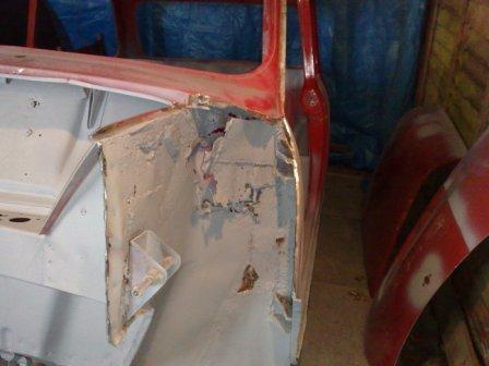 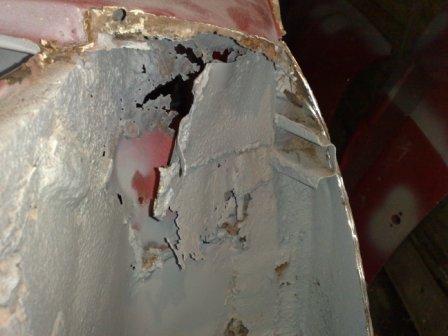 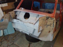 The cutting and grinding continues, I've tackled the right hand side first, and this reveals the extent of the patchwork that has been added over the years to keep the MOT men guessing! It would appear that nothing has ever been cut from the car, it's simply been patched from the outside and then patched again from the inside, and when the patches have gone rotten it's been patched again! In some places it's 5 layers thick! The weight and shear quantity of metal being removed is quite incredible. Fortunately the rot is just about restricted to the inner wing panel and these are available complete from "Heritage Ltd". However it has eaten into some of the scuttle, for which there are convenient repair parts available. Plus the front of the door shut is not too great either, again a repair section is available to save having to remove and replace the whole part. So once all the old rusty parts a re removed there's certainly a big hole! 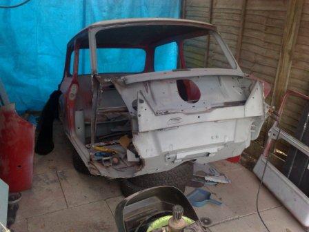  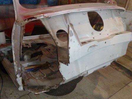 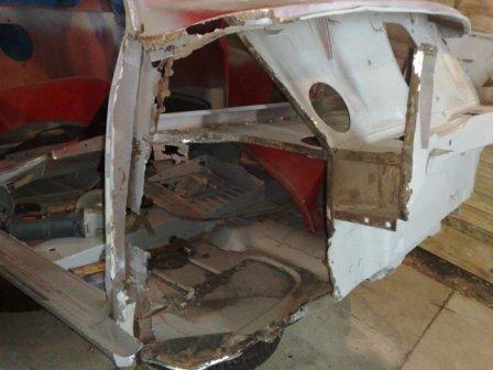 It's been a busy few days! This update will take you through the gearbox rebuild, and the re-assembly of the engine (head block and gearbox). After this I have another exciting update to take you through as I've had the excitement of getting the shell back from the shot blasters. So I can show you a few interesting bits and pieces that will definitely need some attention! But first things first, "The Gearbox". Having split it from the bottom of the engine before reconditioning the block and bottom end, the first job was to completely strip all the components and assess them for wear. Although I found a missing thrust washer on the crank for the primary gear, which explains some of the whining noise, I still need to make sure there are no other maladies deeper inside the box itself. The first of those maladies became evident very early on, the outer input shaft (1st motion shaft) bearing was starting to disintegrate, that is the plastic carrier for the rollers was in pieces, luckily the rollers were still in place and there was no sign of damage to the shaft, so a new bearing, complete with the race that sits in the clutch housing was sourced. 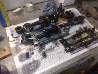 Gearbox Internals Ready for Cleaning and Inspection Once all the parts were removed (see pic) the inspection continued. The baulk rings all appear fine, very little wear (confirmed by the fact that there were no gear selection issues when driving the car). The other bearings were also all ok, until I got to the ones inside the lay-shaft (2nd motion shaft), they were showing quite a bit of pitting and I know they are a Mini weak link, so I've replace both of those too. Otherwise, all the gears are fine, the shafts don't have any wear either. the selectors, detent springs and detent balls just needed to be dug out of the sludge in the bottom of the casing (here’s an obvious tip, make sure you have all the exits covered when you put an airline into the hole to help move the stuck detent balls! if not the best that will happen is you will be showered in oily sludge but that will seem minor if you get shot by a ball that you have missed!) Once apart everything was cleaned thoroughly (good old Nitro Morse to the rescue once again), the empty casing also had a jet wash before being thoroughly dried. 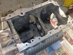 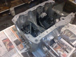 Re-assembly started with the selectors, just a little grease on all the moving surfaces is enough, after all everything will be submerged in oil down here in the bottom of the sump well before the engine is started. Then the output (or 3rd motion) shaft is re-assembled. It's worth knowing that unless you're changing the big primary shaft bearings the Mini gearbox can be re-build without the need for a press. This is becaues the gears and syncro hubs are retained by an ingenious spring and plunger arrangement in the base of the shaft splines, it's a bit of a fiddle to assemble, but it works really well. I guess it's a system that's too expensive in today's manufacturing world (it requires a drilling in the shaft, a spring, ball, plunger and special washer, as opposed to a press fit) but it certainly makes re-conditioning a doddle. 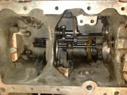 Selectors reassembled 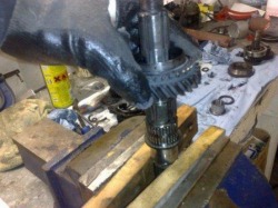 1st gear going onto the output shaft 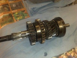 The complete output shaft (gears and syncro hubs) So once the shaft is back together, it's time for the major re-assembly to begin, making sure to trap the oil pick up strainer into the casing before the lay shaft is fitted (it's a big job to fit if you forget it and find it on the bench at the end!) Once it's all back together it's ready for re-assembly to the block then the whole assembly gets turned back up the right way and the head can go on! With nice clean aluminum clutch casing and gearbox married to the shiny green block and head, it's all starting to look rather special! (even if I say so myself!) 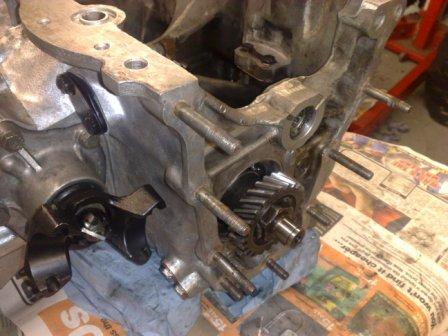 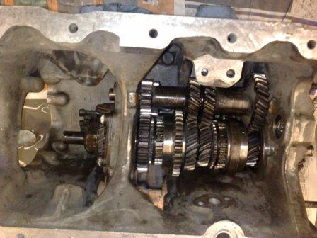  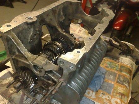 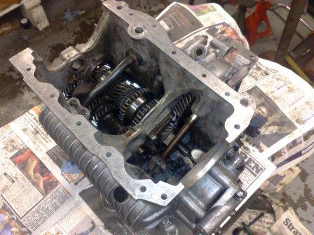 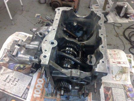 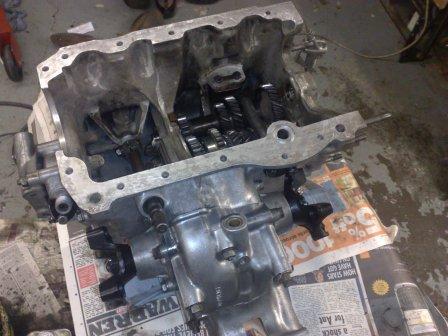 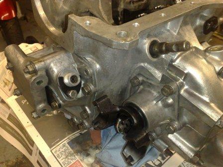  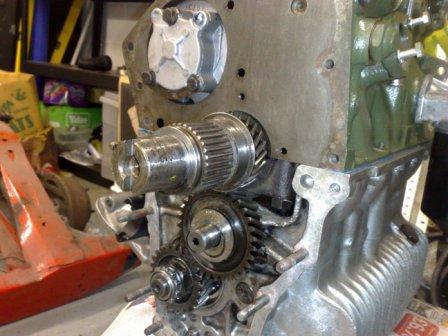 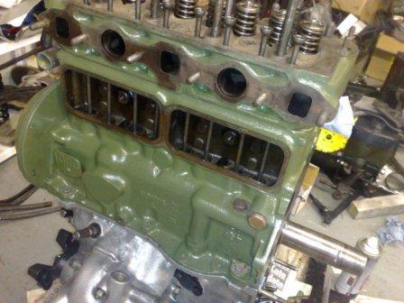  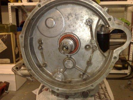 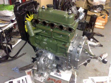 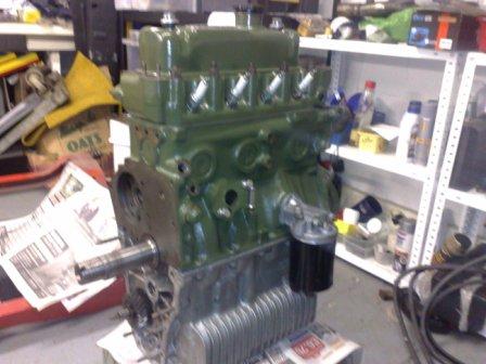 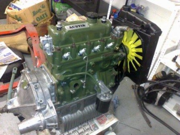 |
AuthorRob Russell. Archives
May 2012
Categories
All
Click to follow the Blog on Twitter
|
 RSS Feed
