• Home
  • About Us
  • Projects
    • Grey Mini Project
    • Peugeot 205 GTI Restoration
    • 1969 Mini Cooper Project Description >
      • Blog for Mini Cooper Restoration
      • 1969 Mini Cooper Before Pictures
      • 1969 Mini Cooper During Pictures
      • 1969 Mini Cooper Finished Pictures
    • 1975 Mini Pick Up
  • News Blog
  • Contact
Born Again Cars

And.... here we go again! (on the other side)

5/24/2010

0 Comments

 
After my last Blog post, my motivation was up, the chance to finish the right side of the car was definitely in sight.
 
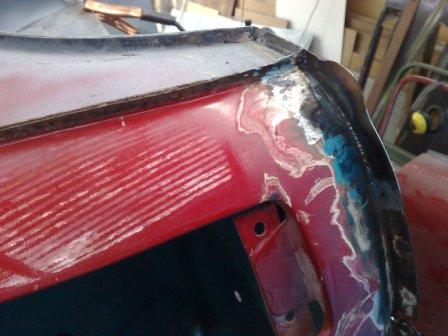
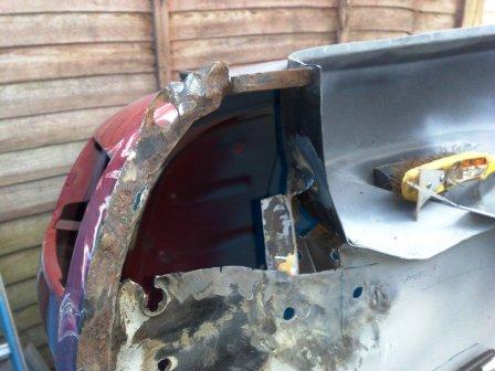
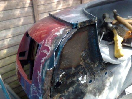
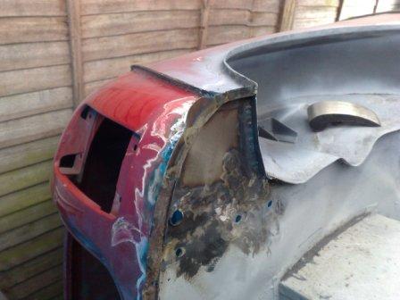
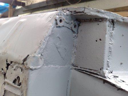
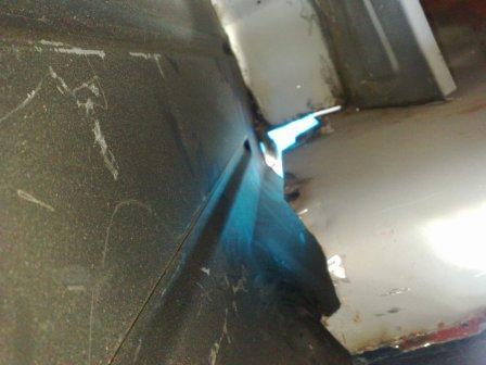
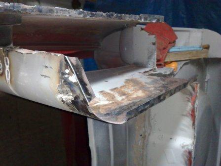
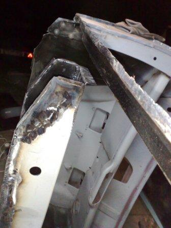
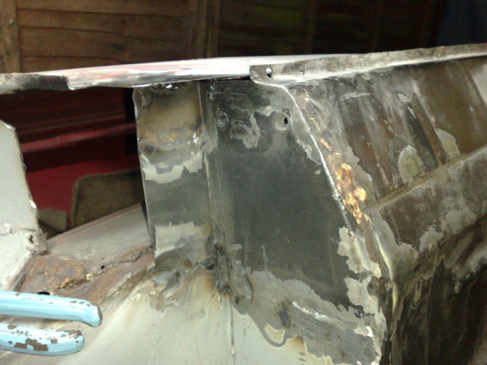
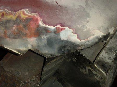
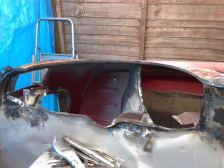
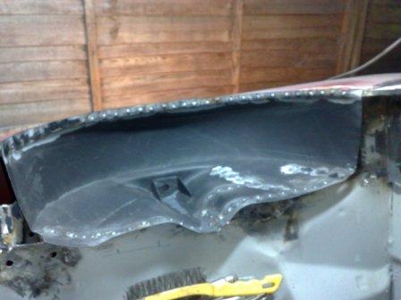
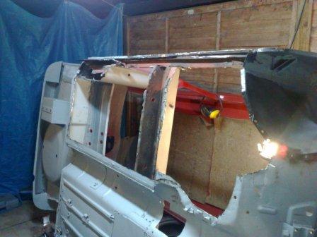
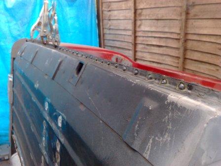
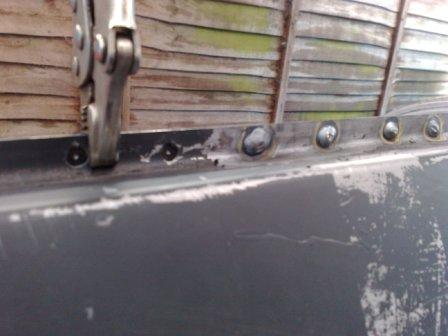
The final area that needed to be sorted out was the corner of the boot floor and with it the corner of the body and rear valance mounting return. As you can see in the pictures this all went well and the corner was pretty quickly solid and sound.
Picture
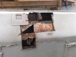
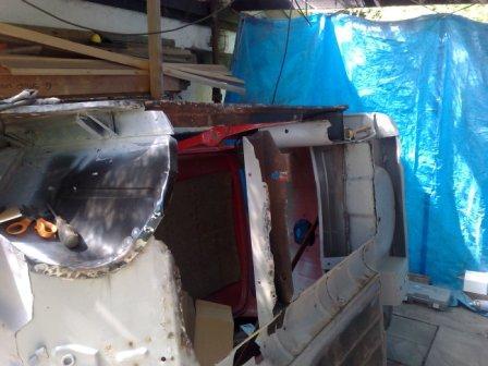
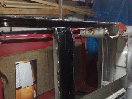
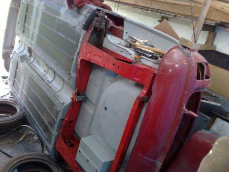
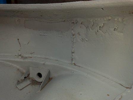
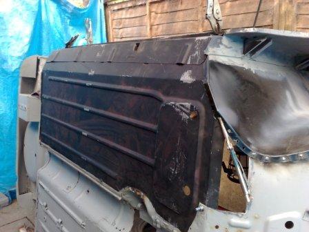
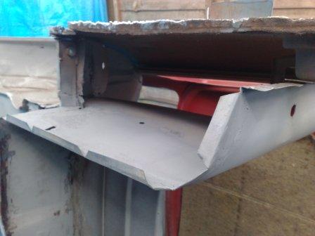
So it was time to roll the shell over and start work on the left side. But as I was getting ready I realised that all the dirt, grinding grit, dust and remaining shot blasting sand had been falling and gathering on the lower side (the left). Not a problem to clean up where I could see it, but there was also a whole load that was trapped in the cross member, which I didn't want to stay there as the shell rotated. So I cut a hole through the sill and let it all out. There was a fair quantity in there so I'm glad I did. The picture here shows the hole and also the blocked up jacking point in the sill (not much use to anyone!).

Then finally, after a good clean up of the rest of the car and my work space it was time to roll the shell over.

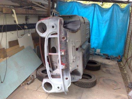
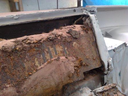
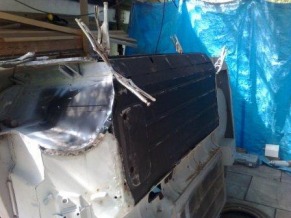
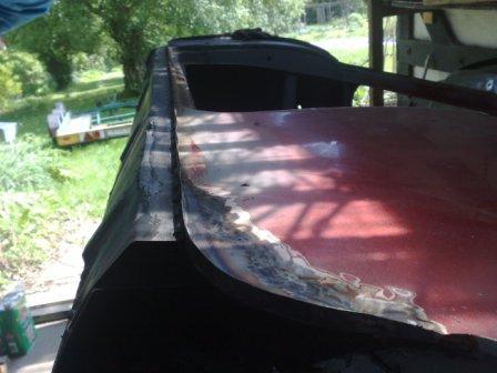
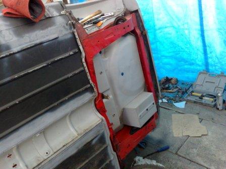
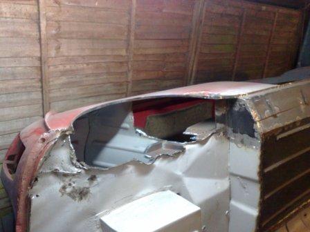
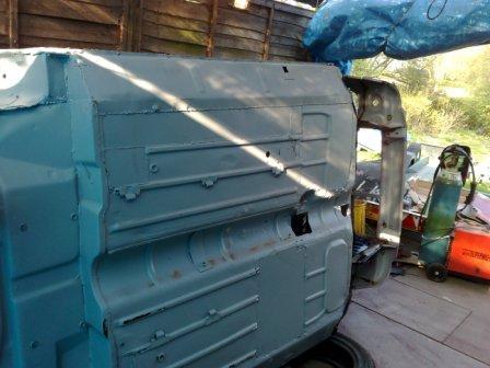
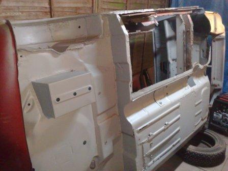
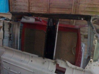
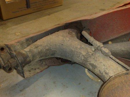
As you can see the condition of this side is very similar to that of the other, the rot is evident across the whole floor pan and has also started the "nibble" into the parts above the floor. The cross-member and the companion box are if anything slightly worse on this side. Which means slightly larger fitted repair sections will need to be made.

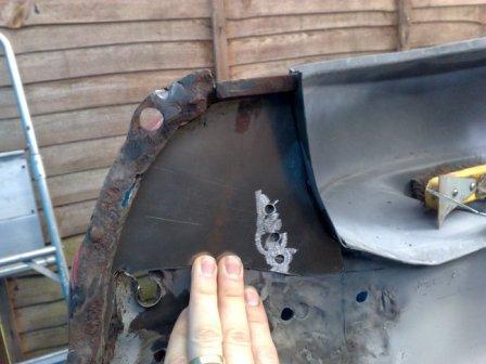
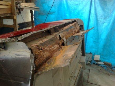
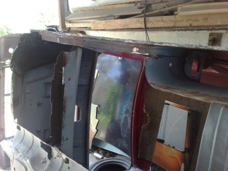
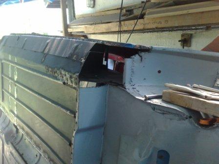
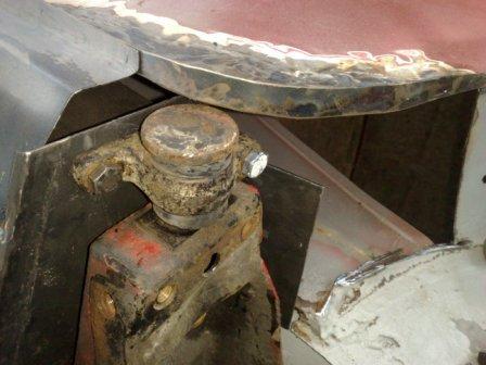
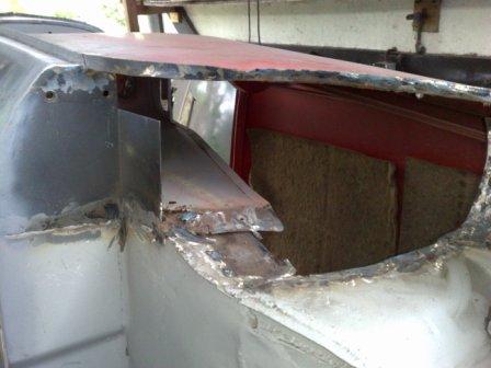
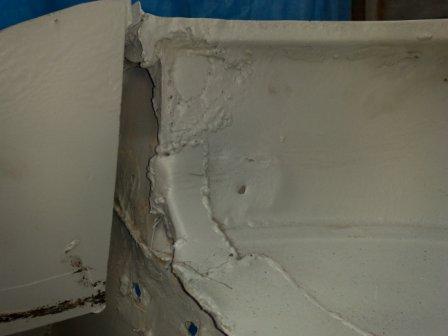
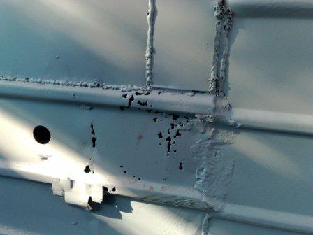
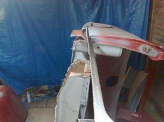
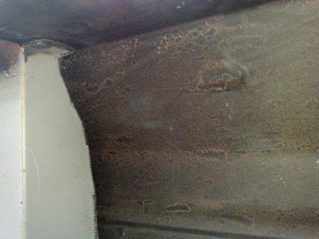
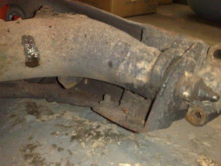
The next shots show the removal of the sill and floor pan. The first two pictures illustrate just how much of the shot blasting sand has found its way into the inner parts of the body through the rust holes. So my tip of the day would have to be "Don't use shot blasting to strip your car unless you are going to open every cavity during the restoration process". The last thing you want is to be carrying 10kg of sand round for the rest of the car's life!
Picture
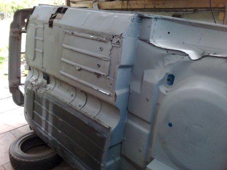
With the old floor and sill removed I can then start the process of trial fitting the new panel. As with the other side I'm using a Heritage half floor and 4" sill panel assembly. These come with the Jacking point and the piece of the cross member that sits inside the sill (to reinforce the jacking point), already fitted. The 4" sills are what would have been fitted to this, a Mk2 Mini, originally.

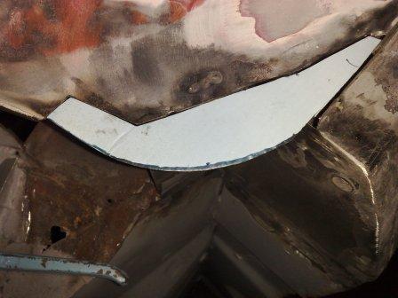
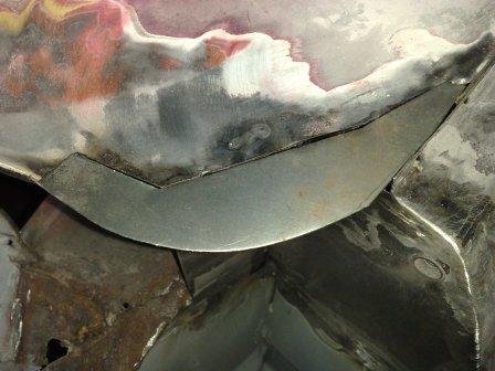
Once in place I can then make the templates for the sections of cross-member and companion box that I have had to cut away. These I then transfer into metal sheet and carefully file to a final fit, before they are welded in place. To finish the job I grind the weld back so the repair is invisible.

Then, once all the areas that won't be seen again are given a good coating of rust protection it's time to weld the floor into place. As always before and during the welding process I'm careful to check the alignments and dimensions to make sure that there is no heat deformation and that all the critical points are in the correct position.
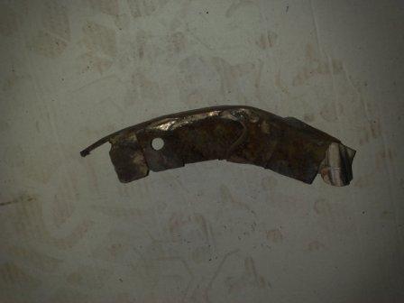
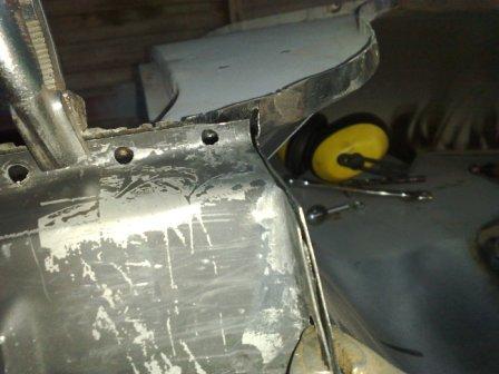
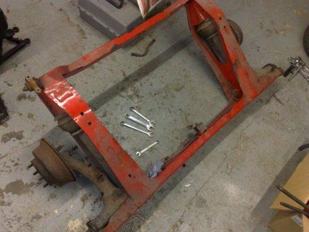
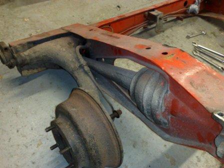
Next it's time to fit the Subframe mounting panel. As you would imagine the alignment of this is absolutely critical. If it's wrong, the Subframe will not sit straight in the car and the result will be a Mini that looks like a crab when it drives along the road.

So to get this right, I use the rear subframe as a jig, which picks up on the three mounting locations that remain on the body. With the subframe secured tightly to these (I have fitted new rubber bushes to ensure a tight fit), There is only one place the fixing panel can go. Which is interesting because it needs a little modification to allow it to fit in this position. So I take a number of measurements to make sure I'm doing the right thing before I'm convinced the panel is the part that needs to be modified (it's only a matter of bending along a slightly different line).

Then after another check it's ready to be welded in place. (Always remember, just like your Dad told you, if you measure twice, then measure again, you'll only have to cut (or in the case weld) it once!)


And that brings me up-to-date! If you're reading this for the first time please find me on Facebook or Twitter (Rob Russell) and you will receive notification when I add more to the Blog. Which will be very shortly I hope - after all my motivation is still high, driven by the good progress being made, so I can't slow down now!
0 Comments

Right Rear Wheel Arch - Out with the Old and In with the New!

5/16/2010

0 Comments

 
Here's another update, a fairly quick one this time, to show you the new left rear wheel arch and subframe mounting. Which means the left hand side is virtually finished! Wow, it does feel like a long haul, but once the shell is flipped over and I'm into the right hand side I hope I will be able to see the end of the grinding and welding tunnel!

Here are some pictures showing the new subframe mount. I used the subframe it self to align the fixing holes but unfortunately my camera had a freaky day and I have lost the shots of that operation. So if you can stand the suspense, I'll have to record the process when I fit the simila panel on the other side.
Next up is the rear wheel arch, as you can see it was in a pretty dire state. As with the rest of the car it had been patched, but the rot was on display for all to see. Why it had not been cut out before the patches were fitted I can't work out? Not to worry though, it will all be replaced, rot, patches and all!

These are a few "Before" pic's.
The removing process is not particularly straight forward when it comes to Mini rear arches, mainly because they 'key' into so many of the surrounding parts, the rear 3/4 panel, boot floor, seat back, subframe mount panel, rear seat pan, the 'companion bin' and also a couple of strengthening gussets that run the load from the rear subframe mount up into the arch.

So care is the order of the day when the grinder is "at large". The pic's below show what I have ended up with....
During the removal of the rear arch it became apparent that the bottom corner of the 3/4 panel was in a rather sorry state. That's actually an understatement, the truth is it had been well and truly bodged! Using some bent bits of metal (shown in the first picture below) which were basically held in with body filler.

So I broke the filler out and stripped back the rusty metal until I was back on solid ground again. It was then a case of making up a template in cardboard, transferring this into metal and welding it in place.

Because this section has a return on it (which the side trim fits to) I then cut a strip of sheet metal and welded it into position. To produce the infill piece with the return as one single piece would have been pretty much impossible without making a tool to use in a press. However with good welding my method is just as sound but it took far less time.
I then had some making good to do, to make sure all those panels that key into the rear arch were in pristine condition. This meant a few more infill panels and some more repairs to return sections. The shell, ready to receive the wheel arch is shown in the first two pics below, while the second two show the arch being fitted. Note the holes for the spot welds (or puddle welds). The ones on the inside edge of the arch pick up the seat back and strength gussets.

And there you have it! the right side is pretty much complete - just a little work on the rear corner and valance before i can flip the shell over and start the flooring process over again. Hopefully I will be well into that for the next blog update.
0 Comments

Roll Over Time

5/5/2010

0 Comments

 
The grinding and welding has been carrying on unabated over the Bank Holiday Weekend, sorry neighbors! (although the rain probably kept most of them safely indoors and behind double glazed windows!)

So what's been happening, well...... The front panels (two wings and front nose part) have been welded into place, using the front subframe as a jig and picking up the inner wings in various places. I also took some time to strip the paint completely from the front panel, this is probably me just being pedantic, but I think the build up of a number of paint layers over the years tends to dull, or blur if you will, the edges of the panels that are on show at the front of a Mini, round the head lights for example. By starting the paint process from bare metal the end result is much more "in focus" and of course original looking too.

Once this was complete and i was a nice shade of pink from the paint dust it was time to get on with replacing the sides of the floor pan. I'm fortunate because the exhaust tunnel arch has virtually no rust evident, so I can leave that structure in place and also the cross member that the seats fix to is in a simila condition. So just like with the front panels, if I tackle one side of the floor at a time the body remains ridged and there is no chance of distortion.

To get good access I have rolled the body onto one side, carefully resting it on some old tyres at the strong points in front and behind the door and at each end of the roof. I can now clearly see the right floor panel that's going to get the attention first. 
Once safe on it's side it's time for the "Flintstone" conversion! I carefully cut out the floor to open up large holes infront of and behind the cross member. Then I go round the whole panel in detail and grind back to the solid parts of the upper panels. Unfortunately the rot has taken the return sections of the pocket next to the rear seats and a small section of the cross member. These will need to be templated and made as fitted sections that I can weld in place. However on the whole the rot is restricted to the floor. The first picture shows the same story that I have found elsewhere, in the back section there is evidence of at least three layers of sill that have been fitted over each other during the years. At least it shows the car has been used and enjoyed I suppose.
Picture
You can see in this picture that with the cross member still providing support the sill remains nice and straight.

Now that the old panel is out, I can trial fit the new part. Being a Mk 2 Mini it still has the bulge in the floor where the floor mounted starter button sat in the Mk 1version (a feature to look out for if you are checking a Mk1 or Mk2 for authenticity). So I have to modify the new panel slightly to fit round this bulge and also cut it exactly to size at the joint along the exhaust tunnel. I do this by clamping it in place, then I paint along the joint with primer to give me a line that I can carefully cut along. When it's all done it can finally be placed into the completely correct position.

When in place I can go about making the templates for the missing parts of the luggage box and cross member. I do this in cardboard first and then transfer the shape to a piece of the correct gauge steel sheet. It's thin enough to cut roughly with snips and then file into the final "fitted" shape. Then I remove the floor to allow me to weld them into place.

The third picture below shows the gap to be filled at the bottom of the luggage box. The fourth picture shows my panel (with the correct returns) welded into position.

Picture
The cutting and prep work is nearly complete, all that remains before the floor is fitted is to give the areas that will not be seen again a good coat of rust protection, and then the final fit can begin.

I clamp everything in place and start the welding at the front outside edge of the floor pan. This is a critical point to get right, it's where the inner wing, the floor, the bulkhead and the sill all come together, so plenty of alignment checking is needed to make sure it's all clamped in the right place (shown in the first picture below), prior to 'sparking up' the welder. The second picture shows this area complete. I then carefully work round the rest of the panel.

Next up will be a repair section for the rear subframe, front fixing (a notorious Mini rot spot, as mud and grime tend to collect here between the subframe and the body). But before I can do that, I strip the radius arms out of the rear subframe, to make it a little lighter to handle. It's going to be used as a jig to make sure I get the fixings in the right place (just like I used the front Subframe earlier). It feels good to use a spanner again, I've been attached to the welder and grinder for long enough!

So that pretty much brings you up to date. I have to say, I can't wait to get to the point where it can go for painting. This part of the whole restoration process is quite intense, because the consequences of getting something wrong are quite high, but at the same time it's also very repetitive, not to mention noisy and dirty work. This tends to lead to a very high intake of cups of tea to keep the concentration and motivation up!

Thanks for reading, please check again soon for the next installment!
0 Comments

    Author

    Rob Russell.
    Learn all about me, just click here

    Archives

    May 2012
    April 2011
    September 2010
    August 2010
    July 2010
    June 2010
    May 2010
    April 2010
    March 2010

    Categories

    All
    Body
    Engine
    Engine & Gearbox
    Interior
    Suspension
    The Beginning

    Click to follow the Blog  on Twitter

    RSS Feed


    Home
Powered by Create your own unique website with customizable templates.